
Reed Relay Reflections
Early experiments in Time Domain Reflectometery
Mid-twentieth Century Telephone service in the United Kingdom(UK)
In the mid-twentieth century virtually the whole of the United Kingdom public telephone network was operated by a government department, the Post Office. (Internationally sometimes abbreviated as BPO, for British Post Office, though never a formal title). At the time it was accused of being slow to replace the electro-mechanical, step-by-step, or Strowger switching system used in all automatic exchanges in the UK. Arguably the fact that the Post Office had its own world-class telephone laboratory with ideas of its own, some too advanced for the current technology, (i.e. time division switching), caused some of the delay. It was obvious that new methods were needed but which new methods? After all the present system had given solid service, long enough for some exchanges to replaced more than once with the same system.
In the UK a telephone switching centre is known as an ‘exchange’. It is said that this is because in 1879 the first telephone switch in Birmingham was installed in 'Exchange Chambers'. An exchange was a building in which business trading was carried out. The activity of 'trading' telelephone calls, plus the name of the bulding, stuck in the public mind and the name became generic.
Standard Telephone & Cables (STC), New Southgate, London
From 1972 to 1975 I worked for Standard Telephones and Cables (STC) in their Electronic Switching Division (ESD) at New Southgate, London. STC was a very well organised company, each division had its own two-digit number which preceded all of its department and part reference numbers. In the case of ESD this was 32 and my section, Apparatus and Component Evaluation, 32364, lead by the inspiring and innovative Ian Gregorig, was part of Test Engineering, 32360.
At that time the main work of ESD was producing the TXE4 telephone exchange for the British Post Office, the second type of electronic exchange to go into volume production in the UK. TXE4 was a large exchange, capable of growing to a capacity of 40,000 lines, suited to the larger cities of the UK. STC had been the design contractor and would go on to manufacture the first batch of these exchanges under non-competitive arrangements. The design would then be passed on to the other two major contactors at the time, Plessey and GEC. Plessey had been the design contractor for TXE2,the first production electronic exchange in the UK. TXE2 was a small exchange, suited to the larger rural communities. The two types had little in common except that they used electronics for control, with a matrix of reed relays performing the switching function.
The Reed Relay
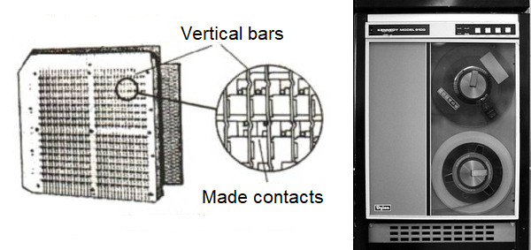
The use of reed relays was relatively novel, it was certainly a big change from the large open contacts of the traditional telephone relay or selector which needed teams of maintenance staff to clean, set and lubricate. The reed switch consisted of two iron blades set inside a glass tube such that they overlapped but didn’t touch. When subjected to an appropriate magnetic field the two blades would bend towards each other, the actual contact surfaces being gold plated. With the magnetic field removed the blades would part and regain their original position. The result was an electrical switch sealed in an inert atmosphere so, unlike the ‘open’ contacts of a telephone relay, it couldn’t become contaminated by dirt or corrosion, promising a long and trouble-free life.
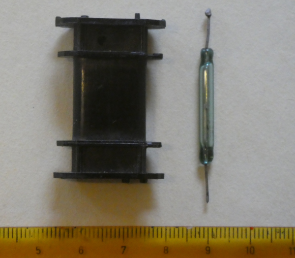
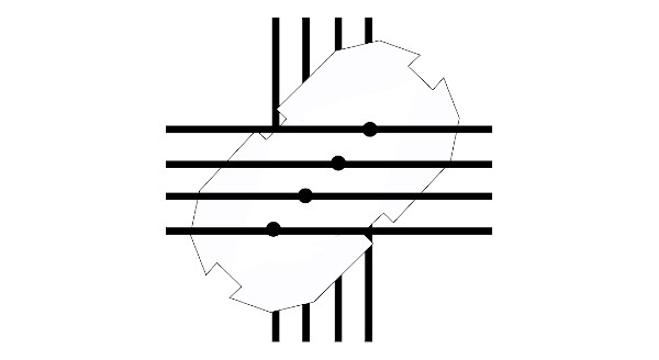
Each reed formed part of the magnetic circuit, four reeds forming the core around which the relay bobbin was mounted. The Plessey system had the reeds arranged as a square when viewed from the end. Because each relay formed part of a rectangular switching matrix one end of the relay was wired horizontally and the other end vertically. The ‘square’ bobbin had four metal tags at each end connecting the four reed ends to the side of the bobbin, the other end being connected to the adjacent side. STC designed an oval bobbin in which the reeds were mounted side-by-side. By the simple expedient of mounting the bobbin diagonal to the lines of the switching matrix this relay did away with the extra metal fittings. One set of reed ends were directly soldered to parallel printed circuit tracks and the other ends were welded to parallel wires that in turn landed on the printed circuit board. Arranging the relays in this way decreased the magnetic efficiencies but significantly reduced the cost per switching cross-point.
'Sticky' Reeds
Within the industry there were concerns that the reed relay might not be robust enough for the job, given the size of the contacts. In particular it was thought that the contacts might stick or weld together if overloaded. That wasn’t easy to prove as the act of pulling out the switch from the racking could be enough to clear the fault, i.e. break the supposed weld.
Around that time STC had an excellent reputation for the quality of its gold plating and was allowed several manufacturing concessions to use less gold than its competitors. Gold plating isn’t necessarily uniform, there are peaks and troughs and if the troughs are deep enough the plating fails to do its job. One way to avoid that problem is to insist that more gold is used, filling in the troughs but also raising the peaks. If however the uniformity of the plating is improved the height of the peaks can be reduced while still leaving enough gold in the troughs.
Before I began working with section 32264 Ken Stuckey had designed a test set with a maximum capacity of 200 reeds, divided into ten groups. Each group could be operated independently of the others. Switches allowed different load conditions to be applied for the duration of the test. All reeds were operated ten times each second for a pre-set number of operations. Failures were recorded on an adjacent printer which identified the reed, failure mode and number of operations.. This test set was operated more or less continuously. Samples of STC reeds were tested on a routine basis and from time to time batches of competitor’s reeds were tested too, if nothing else to show that our production concessions were justified.
I Am Set To Work
My initiation into the work of 32364 was very fast. Ian Gregorig said they had a counter-timer design that someone else had started but that it didn’t work. It used some rather nice dual-in-line integrated circuits made by Texas Instruments that included a red led dot-matrix display and counter. Because the counter and display were on the one chip it was possible to use a more complex display driver than the usual seven-segment displays that were becoming common.
In short time I had discovered and corrected the design error and put the counter to work. In retrospect that was the wrong thing to have done. The junior engineer should act dumb and then be put on a graduate apprenticeship scheme where they are whisked through various departments and, because they aren’t stopping, given glowing reports. I had shown myself to be a competent engineer and was put to work at once.
Ian Gregorig's Experiments
Ian Gregorig was a physicist by training but knew a lot about electronic design. The physicist in him probably caused him to ask questions that others hadn’t done. Some of these were related to what actually happened when a switch contact closed. He had been doing experiments using a pulsed mercury-wetted reed relay, current probe, oscilloscope and camera. The mercury-wetted reed included a small amount of mercury on the contact surfaces, the idea being that there was no ‘bounce’ when the contacts opened or closed, something that an ordinary sprung reed is inclined to do. By pulsing the relay it was possible to generate a ‘static’ trace on the oscilloscope than could then be captured for later examination by using a Polaroid camera. The Post Office laboratories were probably doing something similar at that time as Ian would talk about ‘circuit models’ that they were developing to ‘explain’ what they saw.
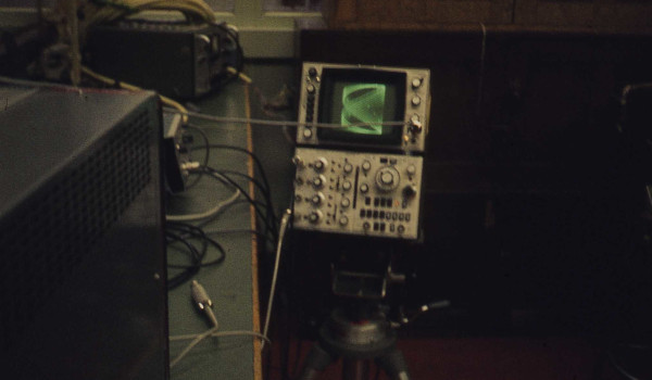
I started to get involved in this work, first as his assistant, and then later pursuing my own ideas. I hadn’t been working on this project long when we obtained a Hewlett-Packard 181A, 50MHz Storage Oscilloscope. Now we were able to capture single-pulse events and, as we learned to master this machine, drastically reduced the number of Polaroid photographs that we needed to take. There were several times when other departments wanted to borrow this oscilloscope and I successfully managed to insist that I came too as I could make the recording that they wanted ‘first time’ and also so that we didn’t run the risk of it being damaged.
One of the curious observations that we made was that there appeared to be a flow of current just before a contact actually closed. Ian called it ‘pre-arc’ current. Whatever it was it demonstrated a constant voltage. Most of the time we used a 50 volt source for our switching experiments, the standard telephone exchange voltage. Thus an open contact would have 50 volts across it, dropping to nominally zero volts when it had closed. What we saw was a drop to about 12 volts, sustained for a short period and then dropping to zero. We tried various contact materials, (there wasn’t much choice), and that did seem to change the measurement by a volt or so. I tried some experiments using a standard reed and found that by keeping the open-circuit voltage below 12 volts I could switch 10 Amps, ten times more than the nominal maximum capacity. We never did any follow up work as both Ian and I eventually left the section. Other people no doubt observed similar effects. It hasn’t been of professional interest since but I am aware of concerns of some people about the reliability of ‘volt-free’ contacts and the supposed need for a ‘wetting voltage’.
Modelling TXE4
No-one knew what currents the reed inserts actually switched while in service. I doubt that the designers of TXE4 knew, they would have worked on the basis of the supply voltage and the circuit resistance, just the same as designers of earlier systems had done. Any inductive or capacitive loads would have produced transients that either were sufficiently quenched or were within the capability of the traditional switch contact. These methods had worked in the past and no-one had the cause or the equipment to discover anything new.

We quickly realised that regardless of the load our reeds were switching something like 0.6 amps into the standard twisted-pair cable used in the telephone business. Switching into two cables would double that, exceeding the nominal current rating of the reed. Essentially we had ‘discovered’ the characteristic impedance of the cable, not something that had been of concern for telephone switching engineers in the past.
All of these early experiments were carried out in the section’s laboratory so we were readily able to change things like cable lengths and methods of termination, the results conforming to transmission line theory, i.e. the magnitude of the ‘inrush current’ was independent of line length, its duration directly related and the magnitude and polarity of any reflection depended on the termination, ranging from open circuit through to a short circuit.
Generally a matrix relay would be switching onto an open-circuit cable as the control system extended the speech path onto the next switching stage. In the case of TXE4 the A-switch crosspoint would switch a path to the B-switch, then the common control would operate the B-switch, extending the path to the, as yet, still open C-switch.
Early Steps in Time Domain Reflectometry
Ian was coming back from meetings with the Post Office saying that they could explain ‘every glitch’ in the waveforms. I decided that if they could do that so could I. In consequence every photograph that I took became as a child, I knew and recognised them all, so much so that I spotted when one of them turned up in a Post Office report!
Each ‘glitch’ of course was created by some discontinuity in the circuit, a connector, a joint or termination. The position of the ‘glitch’ on the trace was directly proportional to the time taken for the energy pulse applied to the circuit to travel to the discontinuity and be reflected back to the measurement point. In those days oscilloscopes were mainly used to observe the frequency of some phenomena, in the frequency domain, whereas here it was the reflection time that was important, so the name time domain reflectometry (TDR) was coined.
Missing Current Is Found & TDR Reveals All
On the other side of the building was the TXE4 model, run by Jim Kennedy. This was a minimal version of a TXE4 containing at least one example of each equipment rack that would go into a production exchange. Access to the model was limited, the model group had their own test schedule and engineering staff for each of the functions also wanted to observe their apparatus functioning under live traffic and integrated with the rest of the system. When we did get access we found there were problems. As expected the observed waveforms were more complex than those in our lab and it was quite fun to ‘explain every glitch’. More serious was the fact that the ‘go’ and ‘return’ currents were different. The Post Office response to that was to alter their equivalent circuit model to get ‘the right result’. I learned a valuable lesson here, don’t trust models or modellers, especially when the model is tweaked to get the answer that they expect. The Post Office hadn’t solved the difficulty, they hadn’t come up with a ‘why’. I was able to demonstrate that the reason that the two currents differed was that a good half of the return current was using the exchange racking and the other 94 wires in the cable bundle instead. Because there were so many alternative pathways it was easy for these stray currents to be unnoticed, each wire carrying only 3mA or so.
Now that we had a pretty good idea what we were looking for we started thinking about where the worst case situations could be found in the model so that we could justify our time on it. One memorable test involved an outgoing junction relay set, the piece of equipment that supervised the connection to another exchange. Because our model wasn’t connected to the outside world, that would have caused havoc with the public switched network, it was expected that this relay set either wasn’t connected to anything or, more likely, connected back to an incoming junction relay set within the model. They called this a ‘trombone routing’, out and back. The trace that I obtained was amazing! What we were doing in analysing these ‘glitches’ was to become known as Time Domain Reflectometry. Here was a trace that told me that the trombone route was three miles long, an incredible figure, nothing like what we had seen in the lab. Jim Kennedy was a bit dubious, he said it was just some cable coiled up under the rack but he humoured me and fetched out the drawings. It turned out that it was connected to the Enterprise exchange, one and a half miles ‘up the road’, and looped back.
We made a similar discover in a very rare visit to a public exchange. The second TXE4 to be installed in Birmingham, Central, was in the process of being commissioned and we managed to get some time there. The Post Office had taken advantage of the fact that the STC version of TXE4 used extruded aluminium extensively in its construction and was therefore relatively lightweight. This had allowed them to build an extra floor on top of Telephone House to take this exchange which must have saved them a lot of money. When we made a measurement on one of the Subscriber’s A-switches, the first piece of equipment connected to a normal telephone line, we again obtained unusually long times. It turned out that in order to reduce the roof loading on the old fifth floor by the new sixth floor extension the standard steel Main Distribution Frame (MDF), as used by all telephone exchanges at the time, had been housed in the basement, making for unusually long connections between the MDF and A-switch. Time Domain Reflectometry wins again!
STC Management Style
A remarkable thing about this time with STC was its working methods. I remember sitting in a meeting with Dr. Geoff Smith, Technical Manager of ESD, with just one other person, (not my boss), and also in a meeting with the Post Office. They had twelve people representing them and on the STC side it was just Dr. Smith and myself, he had authority of position, I had the authority of knowledge, I had been the one who had done the work. So different to other organisations where, if a junior engineer attended a meeting, so did his boss, boss’s boss and so on.
"The whole of the TXE4 project was battling as hard as it could and right in the thick of it was Technical Manager, [Dr.] Geoff Smith. His understanding of TXE4 was second to none, he knew by sight and name virtually everyone in the Division, he knew pretty well all the project unit and rack codes and he had his fingers on all the key factors that needed constant attention and chasing, whether design, model manufacture or budget. He did not stand on ceremony and he worked up and down the reporting levels without messing about with hierarchical etiquette". - Firm Friends by Stan Springate
STC also employed a maverick, Alec Babb. He had his own office and some degree of seniority. It was his job just to think, to challenge the conventional wisdom. He had his doubts about concepts such as ‘triple redundancy’, where three controllers carry out a task and use majority voting should there be a conflict. He would probably have argued that faults were now three times as likely to occur and that the ‘errant’ controller might have been the first to identify an error and be the first to be locked out. He would certainly have understood Donald Rumsfeld’s ‘unknown unknowns’.
Other Work
As part of ITT Europe the Apparatus and Component Evaluation section carried out work for associated companies in Germany (SEL) and France (LMT and CGCT) as well as other divisions of STC. There was a neat crossbar switch from France (Métabar) that came in a plastic pack, about 300mm square and perhaps 30 mm deep. I think we inherited the equipment that operated the switch and a magnetic tape transport that recorded the result. Over the years we came up with various sampling and measuring circuits, ultimately with a solid-state switch and live display which ensured that we were getting good contact resistance measurements, clear of any contact bounce. Ian would carefully clean the tape transport and the machine would be set in motion with my latest improvements and run for the required number of operations. The tape would be sent away for analysis and then when the results came back we were told that they were unusable. We had done our best with our live monitor but we never knew exactly what went on to the tape so never got it to work. Perhaps we had been supplied with a defective tape drive?
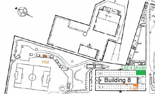
The only other crossbar switch that we were involved with was the TXK3 type, the width of a standard rack. That was so noisy that we got the use of a brick ‘hut’ on the top field. We used that hut for other tests like thermal profiles within racking and heat dissipation from large resistors. The hut came with a fully-serviced toilet so it was quite nice to be able to pop up there to record results and empty ones bowels!
Once TXE4 exchanges started to be commissioned we were tasked to examine failed integrated circuits. Fortunately the company was using the glass-sealed military style package which, with a bit of practice, the top lid could easily be removed. Clearly there were some manufacturing faults, bond wires that had come away from the pads on the die but when we saw a carbon track between the power pins it was pretty clear that someone had managed to put 50 volts onto a 5 volt board!
Along with the routine work of the section, the long-term reed testing programme for instance, there were lots of little jobs that popped up at random. I remember testing pulse transformers, various transistors and laminated busbars. Wire wrapping, the method used to wire up the racks, gave us a lot of work. Test wraps would be checked for contact resistance and then sent away for exposure to sulphur dioxide before being returned to us for re-measuring. In theory the tension of the wrap and the plastic deformation at the corners of the wrapping pin produced a gas-tight joint. If all the parameters were carefully controlled this was indeed true.
Ian had heard some idea that a wrapping pin could be plucked causing the contact resistance to ‘sing’. I designed and built a peak resistance meter. I can’t say that I was convinced that it was producing useable results at the time, it seemed too random, just ‘noise’. However Ian assured me later that the correlation between ‘singing’ joints and sulphur dioxide exposed failures was excellent and he was very pleased.
Characterising reed inserts was another staple and very boring for the lab technicians, carefully increasing the test coil voltage, noting the ‘pull-in’ current, then carefully reducing it to find the ‘drop out’ value. One of my last jobs was to design and build a test set, drop in the reed, press a button, and three values, ‘pull-in’, ‘drop-out’ and contact resistance were displayed. As part of the sequence the reed was subjected to what was known as Isat for 200ms, then the coil current reversed for another 200ms to ‘condition’ the reed. I think it was standard practice to use a current of 10mA at 1kHz to measure contact resistance and to limit the open circuit voltage to 100 mV.
Working with the Apparatus and Component Evaluation allowed me to use many more test instruments that most electronics engineers and, better still, the guidance from Ian Gregorig to use them to best advantage. The variety of the work and the need to design, build and use new equipment quickly was a great experience, like being paid to be a hobbyist!