
Circuit Ideas
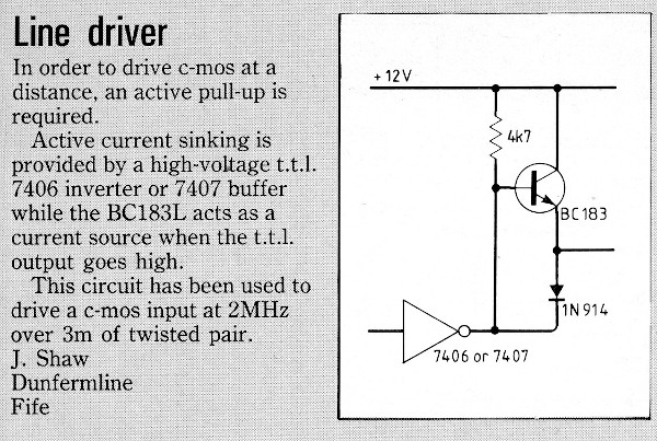
A design for a TTL to CMOS Line Driver submitted to and published by 'Electronics & Wireless World'
I was leading the early development of the automatic test equipment (ATE) for testing the Sea Eagle anti-shipping missile, (then known to us as P3T). This was the first CMOS-based equipment that we had been tasked to produce an ATE for. At that time we had very little information about Sea Eagle, in all likelihood the design hadn't been finalised by the Marconi designers in England, we pretty much only knew the form factor of the boards and the type of edge connector being used.
Around that time I had been seconded to the Advanced Systems Group (ASG) to commission the first components of their new design for an ATE that could comprehensibly test digital equipment. One of the circuit boards in that system was used as a controller and its functions were determined by a ROM, (read-only-memory). Returning to the P3T project it occured to me that a programable clock generator would be useful. Anyone writing programs to test the missile sub-assemblies would only need to use a high-level command in MATLAS, (Marconi's version of ATLAS, a language for writing test programs), to set various clock rates or pulse bursts rather than attempt to generate them with a generic MATLAS function. The MATLAS program wouldn't have been able to operate fast enough to do that anyway.
Rather than design a circuit board for the clock generator I realised that with a different ROM the Advanced Systems Group controller board could be re-purposed. ASG were quite pleased about that as it validated their decision to use a firmware-based design for the controller.
As I recall the board produced clock pulses at various speeds and could be single or multiple stepped. I took care that the mode could be changed 'on the fly', i.e. there was no spurious state change from high to low or vice versa when a new command was executed. Everything worked well, the only problem was that the controller board worked at 5 volts and P3T at 12 volts. The standard way to handle such an interface is to use a so-called 'open collector' driver, the final transistor in the TTL package is rated to withstand a higher voltage than the nominal five volts chip supply when turned 'off' and to be capable of 'sinking' more than the usual current when 'on'. Thus the TTL driver produces an active 'low' signal but relies on an external source, usually a 'pull-up' resistor to produce the 'high' signal. The 'high' signal in this case is determined by the voltage of the supply to the pull-up resistor.
Unfortunately this method doesn't work well when driving capacitive loads, such as a cable. The low 'on' resistance of the TTL transistor is able to discharge the cable capacitance reasonably fast but the current available from a 'pull-up' resistor is obviously limited, producing a slow rising edge to the pulse. That is not very good for the driven circuit which, like all digital devices, has to differentiate between 'high' and 'low' and has thresholds for each. The actual threshold will vary from device to device and a slowly changing input will be interpreted as passing the thresholds at significantly different times, leading to 'race' conditions where two or more inputs which should change state at the same time don't. Furthermore some devices behave in an uncontrolled fashion, even bursting into oscillation, if held in the transition zone long enough.
By adding an active 'pull-up' this problem is overcome, the external transistor providing charging current to the cable when the TTL driver ouput goes 'low'. This design worked for us and I thought no more about it.
A few years later I left Marconi to study for an MSc degree at Strathclyde University. This took a calendar year to complete at which time I was unemployed. Marconi offered to give me my old job back but I wanted a change so I declined their offer. I was then to find it was like being a fresh graduate again, employers were interested in what I had studied but 'come back in five years, when you have had some experience', was a typical response.
Finding myself unemployed for longer than I hoped I looked around for ways to earn some income. 'Circuit Ideas' in 'Electronics & Wireless World' seemed an easy option, especially as I had the simple but useful line driver circuit to hand. I duly sent it off and in due course I received a cheque for £30 in the post. Not bad?
Considering that I already had the design to hand it was quite an easy task, just draw it up neatly, write a description and a covering letter and put it in the post. In point of fact that takes longer than it sounds, so much so that £30 is a meagre 'wage'! Goodness how much time it would take to think up a suitable design from scratch just to get a fee from the magazine, one would surely have to build it and prove that it works too?
I am glad that I submitted it, I am now 'a published author' and it probably secretly pleased my father as he had taken 'Electronics & Wireless World' since he was in his late-teens, (under the title 'Wireless World'), but it is no way to earn a living!