
UK Trident D-5 Missile
A Brief Overview
Disclaimer
This article is derived from a presentation made before a local section of the Institution of Engineering Technology (IET). The aim was to give an un-classified description of the Trident system, particularly as the UK government had recently announced that the missile was to continue in service using a new class of submarine as a launch platform.
The source material is all in the public domain, mostly originally published in the USA, and doesn't necessarily describe the current build state of the missile of which I have no knowledge.
Intoduction
The Trident missile is the delivery vehicle for the United Kingdom's strategic deterrent. The missile was designed and manufactured in the USA and was first deployed by their navy in March 1990 and by the Royal Navy in December 1994. The United Kingdom's government has stated that:
The future of the UK’s nuclear deterrent
The UK’s independent nuclear deterrent is relevant not only for today, and it will remain an important part of our national security strategy for as long as the global security situation makes it necessary. Parliament voted decisively in 2016 to renew our nuclear deterrent and maintain Continuous At Sea Deterrence. This will be achieved by replacing the existing Vanguard Class submarines with four new Dreadnought Class submarines.
Designed and built in the UK, these new submarines will be some of the most advanced machines ever built, employing world-leading and cutting-edge technology to deliver an extremely capable and intensely formidable capability.
Each year, the government updates Parliament on the progress of the Dreadnought Programme. The programme remains within budget and on track for the first new submarine to enter service in the early 2030s.
As part of the renewal programme, the UK will replace its existing nuclear warhead. We are working with the Atomic Weapons Establishment to build the highly skilled teams, facilities and capabilities needed to deliver the replacement warhead programme. We will continue to work closely with the US to ensure our warhead remains compatible with the Trident Strategic Weapon System, used by both the existing Vanguard Class and future Dreadnought Class submarine fleets.
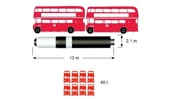
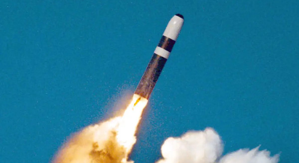
The Trident D-5 Missile
It is useful to get some idea of the size of Trident. Here it is compared to the London bus. The missile is about 13 m long and 2.1 m at its widest, or the length of one and a half London buses. However it is considerably heavier at 60 t or about eight London buses.
Safety and Reliability
Clearly for the missile to remain in service for fifty years or more it needs to be safe and reliable. How is this achieved? Broadly by design, control of the operating environment and maintenance.
Taking these in reverse order, there is a continuous programme of life-testing representative components and assemblies and qualification of materials. This means that problems can be detected and resolved before they effect the inservice missiles. Periodically missile are returned to the maintenance facility and disassembled. All sub-assemblies are removed and parts are refurbished or replaced and the whole tested and reassembled. It is common practice to treat weapon system equipment in this way as by their very nature they spend most of their lives unused yet are expected to work faultlessly when required.
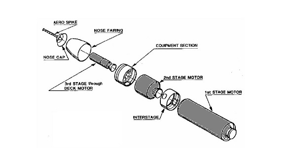
Major Assemblies
Here we can see the main assemblies of the missile; the first stage motor, interstage section, second stage motor, equipment section, third stage motor, nose fairing, nose cap and aerospike.
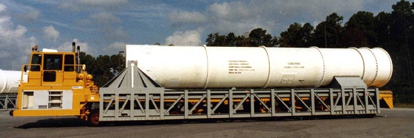
The service environment ensures that the assembled missile is never exposed before use. Missiles stored on-shore, in the Ready Issue Magazine are kept in a horizontal attitude, inside a sealed loading tube. Onboard the submarine they are contained in a launch tube with temperature and humidity maintained between limits.
Missile Handling
Here is the loading tube, which sits on top of an erection bridge. The trunnion arrangement at the left end here, allows the loading tube to be raised to the vertical.
The loading tube is craned onto the submarine and locked down, ensuring that there is no relative motion between them. An electrically-operated hoist attached to the top of the tube lowers or raises the missile in the submarine launch tube.
The submarine has 16 launch tubes, in a 2 x 8 formation. Each launch tube is sealed with a flexible closure or diaphragm which maintains the tube environment even if the muzzle hatch is opened, as shown here.
Finally the missile is designed to be safe and reliable. It uses solid fuel rocket motors, which eliminate leakage problems, insensitive ordnance, that goes bang when it should and not when it shouldn't, linear ordinance in the firing chains, eliminating connector problems and giving immunity from electrical interference. The essential electronic guidance and control systems are housed in screened and bonded packages to achieve Electro-magnetic Compatibility.
The combination of solid fuel rocket motors, linear ordnance and multiple initiation pathways ensures reliable operation.
Solid Fuels versus Liquid Fuels
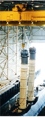
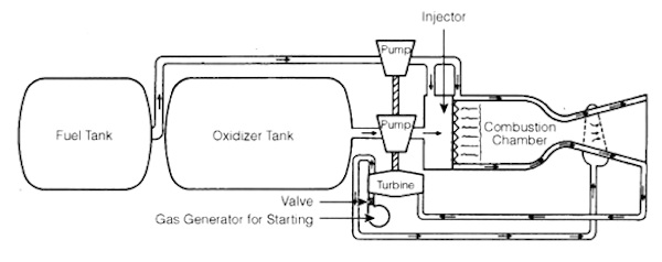
Why use solid fuels when the first production ballistic missile, the German V2, used liquid fuels? Here is a typical liquid fuel rocket motor. It has the advantage that the highest pressures are confined to the combustion chamber, which is strong but relatively heavy, whereas the fuel and oxidiser tanks can be relatively lightweight. However such a system requires pumps to transfer the fuel and oxidiser to the combustion chamber.

Here is a recovered V2 fuel pump. With a rating of some 400 kW it is quite a machine!
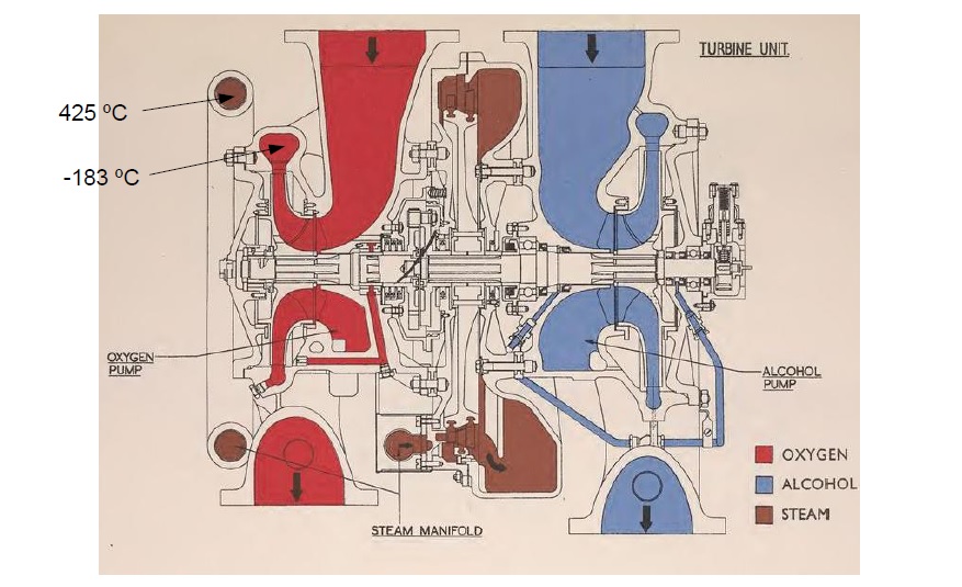
It is even more impressive when one considers that it is driven by steam at 425 celsius and pumps liquid oxygen at minus 183 celsius, with close spacing between these working fluids.
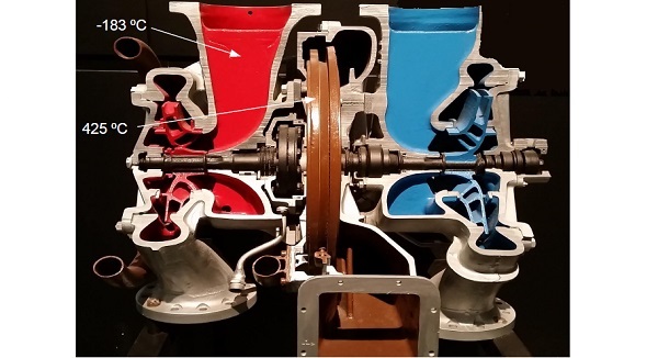
The sectioned pump here shows the central steam driven turbine, (brown), and the liquid oxygen pump, (red). Clearly sophisticated mechanisms such as this don't work in favour of reliability and are best avoided.
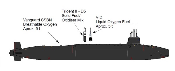
However the main problem with liquid fuels is containing them for any length of time. Almost by definition the liquids need to be very reactive, which can pose many hazards to personnel and equipment if they leak. Even an oxidiser such as liquid oxygen, which might be thought to be benign, is a hazard if it leaks. The V2 missile carried as much liquid oxygen as the breathable oxygen in the Vanguard class submarine. Normally oxygen makes up 20% of breathable air, increasing that to 23% is considered to be dangerous so a leaking V2 doesn't bear thinking about.
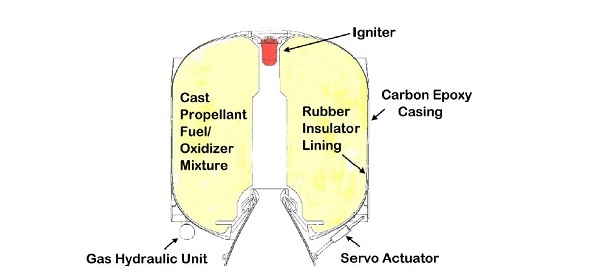
Now instead consider the typical solid fuel propulsion motor. It consists of an outer casing, a rubber insulator lining and, shown in yellow, the cast propellant. At the forward end is the igniter, shown in red, and at the aft end the nozzle, hydraulic actuator and gas/hydraulic generator to power the actuators. The central core is hollow and when the igniter fires it sends a sheet of flame down the core causing the propellant to burn along its length. The gas produced is ejected through the nozzle, producing thrust.
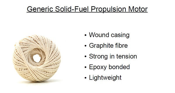
Unlike the liquid fuelled rocket motor the solid fuelled motor has to be strong enough to withstand the thrust pressure. This has been achieved by making the casing rather like a ball of string. Graphite fibre, held in place by epoxy, forms a lightweight yet strong shell.

The shaping of the propellant can be more complicated than that shown earlier. A simple circular bore will increase in surface area as the burn progresses which means that the thrust is least when the motor is at its heaviest and at greatest when the motor is at its lightest. By adopting a star-shaped pattern it is possible to increase the initial surface area and indeed tailor the thrust/time relationship as required.
In this simple illustration as the internal points of the 'star' burn away the sides of the 'star' tend to shorten, compensating for the enlargement of the diameter of the star as the burn progresses.
Motor Ignition
It is clearly essential that ignition of the propulsion motors only takes place when it is required and safe to do so. It is also essential that the ignition process is reliable.
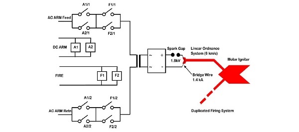
Safety is assured by requiring three separate signals from the missile fire control system and reliability by providing duplication of the interlock system and initiation chain.
To ensure safety at least three signals are required to fire a motor igniter. These are 'AC Arm', 'DC Arm' and 'Fire'.
'AC Arm' is switched over the contacts of relays operated by 'DC Arm' and 'Fire' signals. It will be seen that each of these signals operates two relays whose contacts are wired in parallel so that if a single relay in each path fails the intiation signal will still occur.
The use of an alternating current, i.e. 'AC Arm', isolated by a transformer, ensures that no stray d.c supply can cause ignition.
The switched 'AC Arm' signal voltage is increased by the transformer, rectified then applied to a spark gap. The ignition signal has to be of sufficient voltage to break down the spark gap and have sufficient power to heat the bridge wire adjacent to the detonator. It is extremly unlikely that any stray electrical current either internal or external to the missile will be capable of firing the bridge wire and its associated detonator as a voltage of 1.8kV is needed to jump the spark gap and a current of 1.4kA is needed to rupture the bridge wire. .
The detonator is intimately connected to the linear ordnance system, essentially a thin tube containing a pyrotechic material. The abrupt impulse from the firing detonator causes an explosive event to propogate along the linear ordnance system which terminates against a detonator set against the motor initiator. The linear ordnance system is insensitive to low-speed impulses, such as, say, a hammer blow, so that only an explosive axial impulse applied to one end will propagate to the other end making it an extremly safe method of initiating ordnance events at a distance.
Each ordnance initiator is fed from two linear ordnance systems, each connected to one of a pair of firing units that are operated together, i.e. the firing chains are completely duplicated up until the initiator.
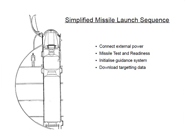
Simplified Missile Launch Sequence
External power is applied to a designated missile. The Missile Test and Readiness system in the submarine runs tests on the missile to ensure that it is fit to fly. The missile guidance system is initialised and referenced to the submarine's navigation system. Target data is downloaded to the missile.
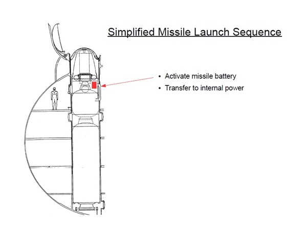
The missile's internal battery is activated and the missile switched from external to internal power.
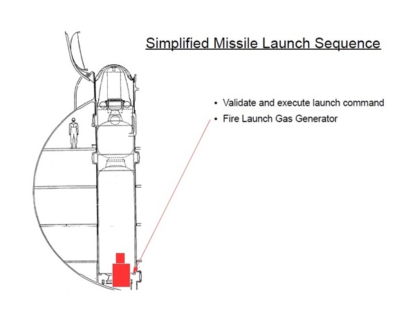
The command to launch is validated and executed. This results in the launch gas generator being fired. This is external to the launch tube. It feeds a mixture of steam and hot gases into the base of the launch tube and this begins to raise the missile off the support ring.
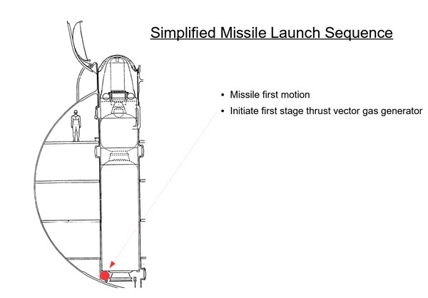
This first motion triggers the operation of the first stage thrust vector gas (TVC) generator to ensure that hydraulic power is available to operate the first stage nozzle servo actuators.
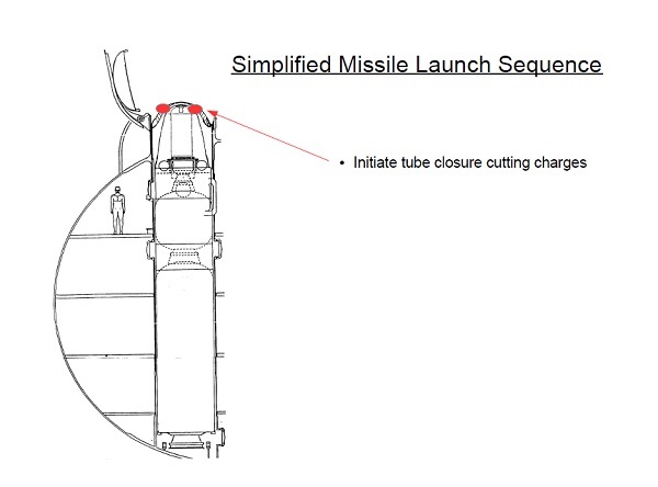
Cutting charges in the tube closure allow the missile to rise cleanly out of the launch tube, the umbilical cables connecting the missile to the submarine are unlatched automatically.
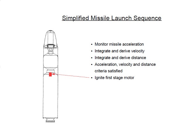
As the missile moves its acceleration is measured and velocity and distance travelled calculated. If these values are within set limits the first stage motor is ignited.
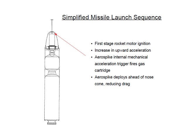
The acceleration given by the boost motor triggers the mechanical initiation of the aero-spike which when deployed greatly reduces drag.
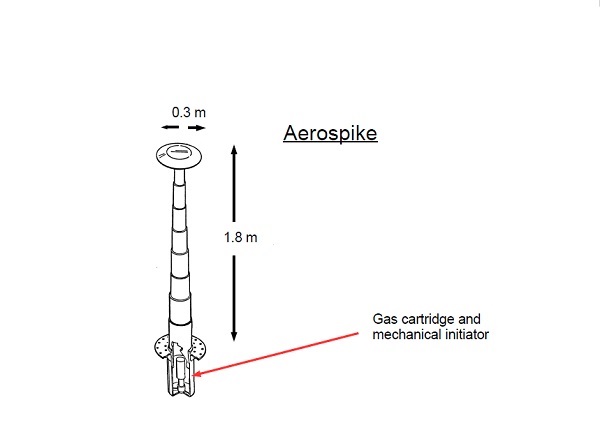
This self-contained assembly contains the mechanical initiator, gas cartridge and telescopic tube sections. The spike extends 1.8 m and carries a deflector dish 0.3 m in diameter.
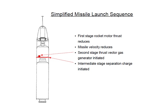
After a minute or so the first stage begins to burn out and the change in missile motion is detected causing the second stage TVC gas generator to be initiated and the intermediate stage line cutting charge to be fired, cutting loose the first stage.
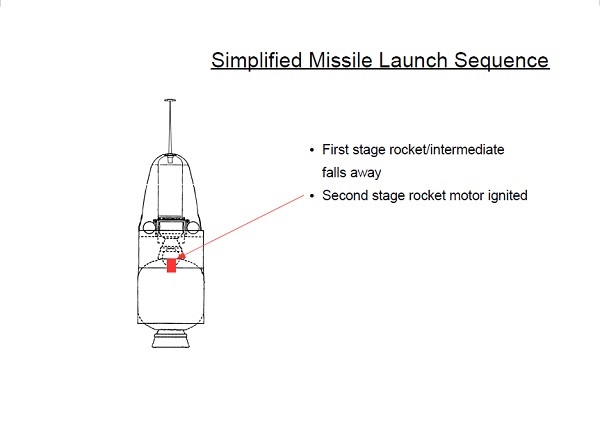
The second stage motor is then initiated and the missile accelerates again.
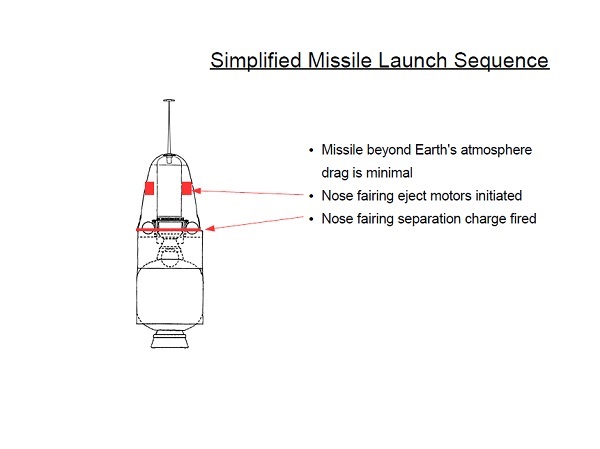
The missile will now be clear of the Earth's atmosphere and the nose fairing is no longer required. Small eject motors within the fairing and the nose fairing line cutting charge are fired, throwing the nose fairing clear of the missile.
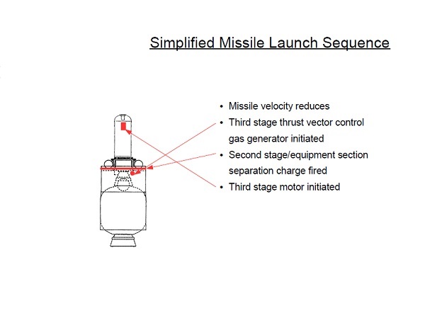
Now after about two minutes of flight the second stage is reaching burn out and the missile velocity reduces. This triggers the initiation of the third stage TVC gas generator, the firing of the second stage line cutting charge and initiation of the third stage motor.
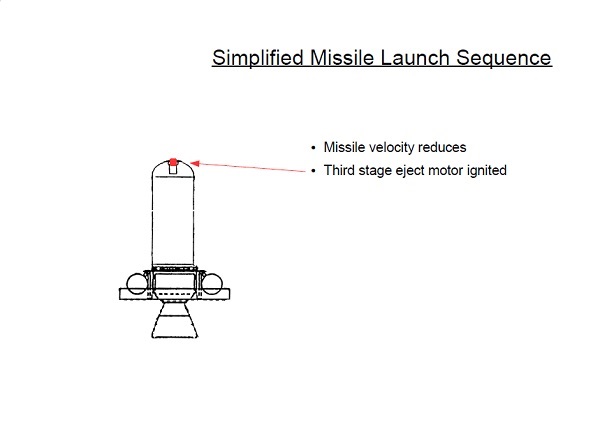
The third stage and the equipment section are now flying free. As the third stage motor reaches burn out the third stage eject motor is fired. This is a small motor set in the forward end of the third stage motor. It checks the forward motion of the third stage motor, allowing the roller-mounted equipment section to carry on moving forward.
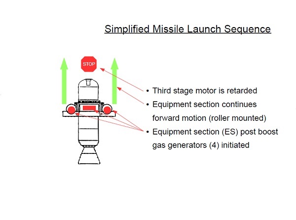
The equipment gas generators are initiated as it overtakes the discarded third stage motor.
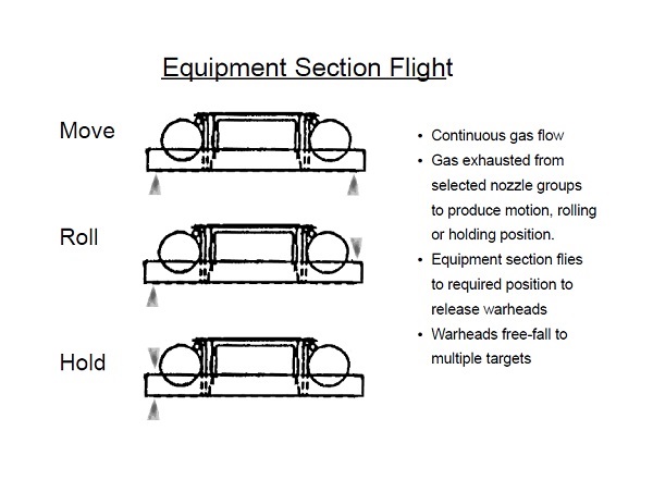
The equipment section is now flying freely. The output from the gas generators are directed through various nozzles so as to steer the equipment section. As the gas generators run continuously nozzle combinations are selected so as to maintain gas flow. The examples show how a pair of nozzles can move, roll or hold the equipment section steady. The equipment section carries the warheads, (not shown). It is flown to pre-determined positions in space at which point the warheads are released to free-fall ballistically onto the designated targets.
It has been said that the warheads can be launched with sufficient accuracy to fall within the central courtyard of the United States Pentagon, (not the most likely of targets!)